|
|
||||||||||
|
||||||||||
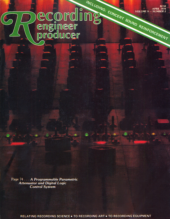
| Crystal Studios - My Story | ||||||||||
| including the Recording Engineer/Producer April 1978 article reprint | ||||||||||
|
Note: my comments are in this purple font. The article, reprinted below, is in black.
The next May, I went to the Audio Engineering Society (AES) convention in LA. The running joke was all my buddies chipped in and bought me a one way ticket to LA... but it was much more serious than that... I found an LA yellow pages and began visiting studios in alphabetical order. Joe Chiccarelli had previously visited LA and came back with the famous line: "In Boston, we have five studios... in LA they have five studios ON EVERY BLOCK!" So I was determined, after reading about all these studios in the trade journals to see for myself. I was able to visit over 40 studios and I gave my resume to everyone I could. Subsequently I got 35 job offers! So I moved to LA, started at Cherokee Studios, and then managed to get a few evening and weekend gigs in other studios doing maintenance, wiring, fixing equipment... ...and I got a few gigs doing recording, and nearly every time I'd go into a studio to record there would be a noisy fader, a crackling switch, a bent pin on a VU meter (!!!) something with a tape machine that needed aligning or fixing... so seemingly every three hour recording session turned into a six hour marathon of fixing things first, (it was called maintenance in those days...) then recording after everything was tweaked. So I made a business card which said "Mixing and Fixing", and it served well.
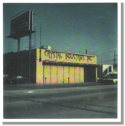
A few weeks went by and I got a call from Crystal Studios (almost next alphabetically from Cherokee, you might notice; Conway was actually next in line) and I went to meet Andrew Berliner. He interviewed me for eight hours. First he questioned me, thinking I was a spy for some other studio. Then he grilled me about all sorts of electronic trivia. Then he more or less took me into his confidence and told me the overall story of the studio and the history of the equipment. He had various partners and associates and staff and friends, all of whom contributed their part to the overall effort. His effort may have started as a hippie studio fantasy but soon turned into an electronic design laboratory right on the cutting edge of what anyone in the industry was doing. From Doctor My Eyes by Jackson Browne in 1972 to an enormous string of hit albums by Stevie Wonder, Crystal was on the map as one of the hot LA studios. A further appeal was that is was a one-stop shop: you could record, and mix and master your album all in one building, and the main recording room was also big enough to hold an orchestra. In the mid 70's Andrew's ideas and eventual implementation actually far surpassed the cutting edge; for their day, all three consoles he built had many industry firsts and absolutely unique circuitry. He and various engineers and techs at the studio also highly modified the industry standard Studer tape recorders and the Neumann disc cutting lathe, and the clean, tight punchy sound you could get from this studio was fast becoming an industry legend. I went to dinner after the interview. Then Andrew called me up and asked if I would come over again. Sure! So after a full day's interview he started in again and then he showed me what he called "the holy file cabinet" in what was to become my office and engineering lab. There was an engineer who, sadly, I never met, who had recently passed away. He worked at Crystal for a number of years, and as the campfire story goes, was one of those white-pocket-protector-nerd-pak engineer types. If you are an electronics engineer or tech this is a very high compliment. So this fellow, Dean, had apparently kept a written technical diary on yellow pads of everything he did or thought about. It was written in a multiple person view, sometimes in the first person, sometimes not; and all the math was longhand, out to an unnecessarily large number of decimal places(!) All the yellow pads were stored chronologically in one of those massive fireproof file cabinets usually reserved for sci-fi movies of secret government installations. The diary rambled on like this: |
||||||||||
|
||||||||||
|
And so on. Clearly the fellow loved ellipses, and went on like that for literally hundreds of yellow pads. His partially-finished prototypes and circuits were laid out all over the room, and Andrew wanted to know if I thought I was up to it -- me finishing building up the breadboards, and taking over from where this previous genius left off. I looked him right in the eye and said, "Yes, I would like that very much." Andrew had built a magnificent and very straightforward recording/mixing board in studio A, and these newer designs were to be used in the studio B board. Then the circuitry was to be expanded upon, (for example the equalizer was made to be 6 sections instead of 5 sections) microphone preamps of a completely new design added, a MUCH larger patchbay implemented, and this brand new board was to be the retrofit in studio A. So I started to put in long hours working with Andrew finishing up the Studio B console and also on the refinements for the NEXT studio A board. It was so fascinating and intense that I just threw myself into the project, sometimes working 16+ hours at a stretch, going home, crashing for 9 hours, then coming back into the cave-like building (there were no windows) until I lost all track of time. All in all, whatever stresses it imposed, I had a wonderful time. Andrew decided to do a preliminary article for Recording Engineer/Producer magazine. He really wanted to do a series of articles, each about a particular section of the recording/mixing board, with an eye to possibly generating sales and therefore building multiple consoles, some outboard equipment, and really ramping up a production facility. The studio itself was called Crystal-Sound, and the "laboratory" R&D part was called Crystalab, which you might notice are Andrew Berliner's initials added. You also might notice that partially in honor of Andrew, I have used the same font for my Soundoctor logo. So here in its entirety is a reprint of the RE/P article of April 1978. Little did we know that the magazine was about to fold a month later... as a typographer I partially attribute it to the fact that the entire magazine was printed in Souvenir font. There are only precious few worse fonts in the world for example hobo and comic sans1 and NO ONE will take anything seriously that is presented in these fonts. There is probably much more to it than that, but hey, that's my opinion and I'm sticking to it... So Andrew and I worked on the story, he wanting to write a large book and the editor explaining just about how many column-inches we had to work with. I did a block diagram (that you will see below) in real Leroy technical pen and ink on matte mylar that was nearly four feet wide. It took almost two weeks! I wish I had the drawing to frame on the wall now! So Andrew kept writing and I would tweak and polish, and eventually, with Andrew pacing back and forth and back and forth in the parking lot smoking a cigarette, (anyone that knows him knows he would do this whenever he was really stressed...) the article was finished. You kind of had to be there. We were actually very proud of each other and this mini-masterpiece we had just finished. |
||||||||||
|
|
||||||||||
 |
||||||||||
| A PROGRAMMABLE PARAMETRIC ATTENUATOR and DIGITAL LOGIC CONTROL SYSTEM |
||||||||||
| by Andrew Berliner, Crystal Sound Recording Studios | ||||||||||
|
As high quality audio systems increase in complexity, super-human demands are being made on the operators of these systems. It is natural for the designer of large recording systems to employ computer techniques to aid the operator in his quest for control as well as to provide more flexibility in operation. The Crystalab system currently under development and in use at Crystal Sound Recording Studios has combined a 40 input channel, 4 output channel mixer with a digital logic system and a 300 megabyte disc storage memory into a high performance, super reliable creative tool.
Modern electronic attenuators are primarily of the voltage control type, i.e., attenuation is a function of control voltage. Such attenuators, using pulse width modulation or analog transconductance methods, are well known, as are their limitations, namely noise, slew related distortion and temperature instability. The cornerstone of the Crystalab approach is the development of the Programmable Parametric Attenuator. Parametric attenuators have been with us as long as electronics. A simple potentiometer is a parametric attenuator; the attenuation being a function of shaft rotation; the ratio of the resistances between the series and shunt legs: essentially an "L" Pad. The Crystalab Parametric Attenuator incorporates and expands this basic concept. Twelve separate "L" pads are connected in series and isolated by an input buffer amplifier and an output driver amplifier. Each pad section contains two switches which insert it or bypass it into the audio signal flow. The values (dB attenuation) of each pad section are chosen in a sequential binary and Grey coded progression. After considerable experimentation, the chosen values are: An electronic attenuator when full on can be considered a unity gain device. The change is gain is expressed as "dB attenuation". Careful circuit design insures the accuracy of each pad section individually as well as additive combinations of any and all sections. Each of the twelve pad sections are addressed by one bit in a twelve bit word. 1,280 different combinations of the twelve bit word provice a gain range from unity to 79.9 dB before off in exact 1/16 dB steps. Pad trimpots mean "step size error" can be made arbitrarily small. Field effect transistors (FETs) were an obvious choice for the switching elements. Their advantages of high speed, linearity and low "on" resistance, are, however, offset by the charge coupled noise as it changes state (on to off and off to on). A major design effort was directed toward designing a floating FET switch with minimal gate/channel capacitance effect and high signal level handling capability. In 1975, after almost three years of research and development, a patent, describing a circuit, embodying isolated gate pullup and constant current pinch off techniques was issued to Crystal Industries, Inc. Singularly the most important ingredient in making this attenuator work, the Crystel-FET Driver, switches signal levels up to ± 12 volts from DC to 100kHz in 2 microseconds. Charge coupled noise is ≤ 90 dBV (relative to input) while linearity is primarily dependent on the FET, 0.01% in "on" mode is average. Each new version of the attenuator solved some problems and created others. For example, in spite of the care taken to provide minimum charge on the gate, the finite noise generated increases with switching speed. When the attenuator slews, (the operator has moved a fader knob...) the least significant bit (1/16 dB) has the highest switching speed. Organizing the pad values such that the highest switching rate occurs at the front of the pad chain allows the noise, so generated, to be attenuated by an amount equal to the total dB attenuation of the subsequent pad sections. Zipper noise is produced by a discrete step size change in amplitude and is exaggerated by the finite time discrepancies of one pad energizing and another de-energizing. It is completely undetectible on complex waveforms such as program material, however, on sine waves, well... so by incorporating a zero-crossing detector to limit the switching of pad sections in to or out of the audio path, only to the time when the amplitude of the waveform approaches 0 volts, all zipper noise vanished. The Programmable Parametric Attenuator as the variable gain element in a professional recording/mixing console offers many unique advantages. In its static mode, at any attenuation (or no attenuation) the audio signal passes through no non-linear or noisy elements. Fifty or more attenuators will track within 1/16 dB over the entire 80 dB range. There is no drift. Slew rates of 125 dB/second with a 1 kHz signal to 2,500 dB/second with a 20 kHz signal are inherent in the design. Another intriguing application of the Programmable Parametric Attenuator is as the control element of a program-controlled gain circuit (limiter / compressor / expander). Such a circuit could peak limit, maintain a constant average level, or expand the dynamic range of an input signal, or any combination. Since 80 dB of control range is not needed, resolution of 1/32 dB or 1/64 dB may be more desirable. The Programmable Parametric Attenuator is the ideal tool for radio and TV broadcast applications. The revolutionary significance of the Programmable Parametric Attenuator is that it provides the missing link between analog and digital. It is the catalyst that integrates the vast resources of applied digital technology into the creative analog musical systems of modern recording studios. This is a data acquisition and management system. In contrast to current automated or "automation-ready" consoles, the "computer" is an integral part of the system. Technically it's "dumb" because the program is hard wired, but its internal 14.2 MHz clock and command time of 70 ns mean the performance and sophistication of a lunar landing. Its operation is easily understood by examining the function of its four main sub-systems: Input, Processing and Control, Storage, and Output. The Input system translates the commands of the operator into its internal language. The block diagram of the digital system components and the flow of data between them illustrates the entire system concept: The simultaneous control of volume of 44 audio signal channels in time increments of 1 ms. |
||||||||||
|
||||||||||
|
A PLAY-BY-PLAY DESCRIPTION OF ONE SCAN OF THE CONSOLE The twelve-bit analog to digital converter using high speed multiplexing techniques, samples and digitizes the control voltage of each of the six submaster faders, 40 input faders, and four line control faders in order. The sequential sampling produces a flow of words. A word is the digitized representation for the number of dB attenuation from unity gain for one time period. First the six words representing the value (dB attenuation) of the six submasters are stored in the six submaster memories. Then, the Channel #1 fader word is entered into the adder. If any of the six submaster selector switches are selected, the values of those submasters are recalled from memory, and also entered into the adder. A word representing the sum of the channel fader and all of the selected submasters results. Each channel is sequentially processed so that one console scan results in the flow of 44 data words from the adder. The flow is then processed by the exponential memory. Here, on a plug-in circuit board the 12 ROM's scale the fader taper. The ability to adjust the dB per inch of travel of all faders while a fringe benefit of digital processing is a unique feature of the Crystalab system.
The function of the Data Multiplexer circuitry is the heart of this high-speed data management system. It is the power of the Read/Write switch. The Data Multiplexer has two data inputs: one from the console faders and the other the "from disc" buffer. The 44 word scans are synchronized such that the Read/Write switch on each channel selects between the two "word 1's". two "word 2's", two "word 3's", and so on until one of all 44 pairs of words have been selected. This composite data is directed to the output circuitry and to the input of the "to disc" buffer. The output circuitry takes the flow of composite data and directs the 44 words to the 44 Programmable Parametric Attenuators as well to the LED dB attenuation readout displays of the fader. The update power of this system effectively allows the operator to alter any of the 44 channels for a period as short as one thousandth of a second without affecting or changing any other channels. The selective Read/Write of each channel on each scan provides a powerful tool. The buffer memory consists of two 11,000 word Randon Access memories. Each RAM has 250 locations of 44 words. The "to disc" RAM receives data from the output of the data multiplexer. At the start of a time zone, say, T200, (note: which is the "T200 time:" referenced in the cartoon panel below) the 44 words of each console scan are sequentially stored, in order, at each location. Each successive console scan addresses the next location. Each time zone is 250 msec. At the end of the 250th console scan the "to disc" RAM is full and all information is shifted to disc in lump and stored in the time zone related block, in this case T200. When T201 starts, the "to disc" RAM is empty and again begins to fill up. This sequence is repeated for each 250 msec time zone. In this way data is entered into RAM in real time but shifted to disc as one block. Meanwhile, just before the start of T200, the block of data at disc location T200 is shifted to the "from disc" RAM as a chunk. When T200 starts, each location is sequentially emptied exactly as it had been entered. The first location that had been filled is also the first to empty. The 44 words of each scan are directed to the "from disc" buffer input of the Data Multiplexer. At any given instant both RAMs are processing the same time zone. The "from disc" is emptying into the Data Multiplexer input while the "to disc" RAM is filling up from the Data Multiplexer output. Time Code The Crystalab proprietary Time Code System allows the synchronization of the master audio tape, console, and disc memory systems. The time code signal generated in the encoder is recorded on the audio tape. As the tape is replayed, each time code reading is interpreted by the time code reader and is translated into a four digit number. The four digit numbers are successively incremental such that 0000 is followed by 0001, 0002, and so on. There are four time zones each second; 2400 time zones for a 10 minute period. The time code signal itself is a modulated 20kHz sine wave recorded at a level as much as 35 dB below reference. One of the problems of existing time code systems is the interference between it and the audio information on adjacent tracks. The unique feature of the Crystalab Time Code System is that it does not require a separate track. It's supersonic frequency and low recorded level make it inconspicuous on the bass or bass drum track. The time code readings are insensitive to dropouts, spurious pops or clicks, and tape speed variations. Overall, the gap between sophisticated electronics and user ease of operation has been narrowed. No longer is "state-of-the-art" a synonym for complicated and difficult to use because the digital control of audio offers the creative engineer a chance to control the equipment and not be controlled by it; it is the mixer's musical instrument which is easily played with understanding and feeling. Designed as an integral element of a complete 24 track mixing studio, Crystalab's new and unique circuits, fabricated with only military grade components and gold contacts on all switches and connectors, underscore the handcrafted quality. Machined aluminum framework and engraved panels, as well as burl woodwork, add strength and beauty to a system where high performance and super-reliability are the first design specifications. The purpose of Crystalab is to enhance the artistry and technology of music recording systems. The tremendous design effort invested in this project is representative of the creativity that is the essence of the music business. |
||||||||||
|
||||||||||
|
||||||||||
|
|
||||||||||
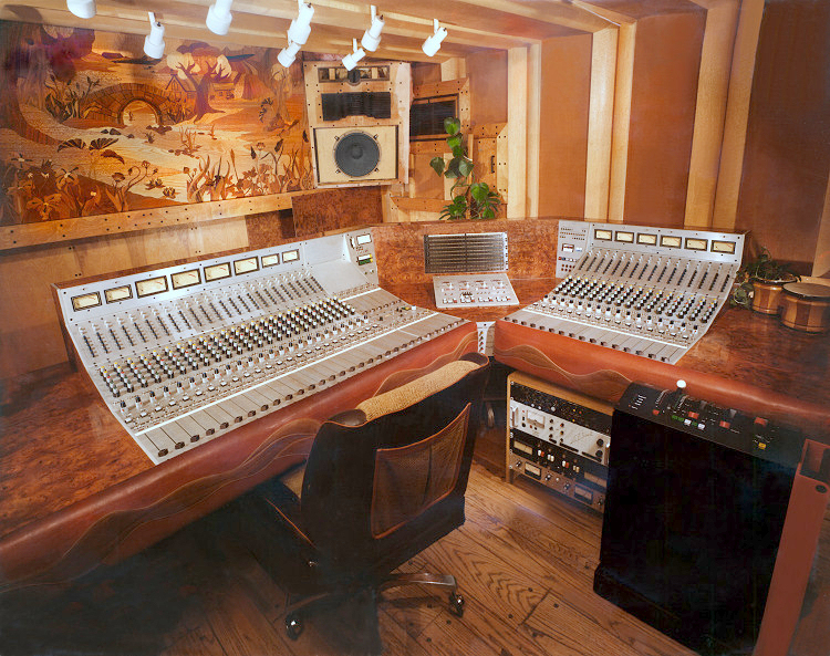
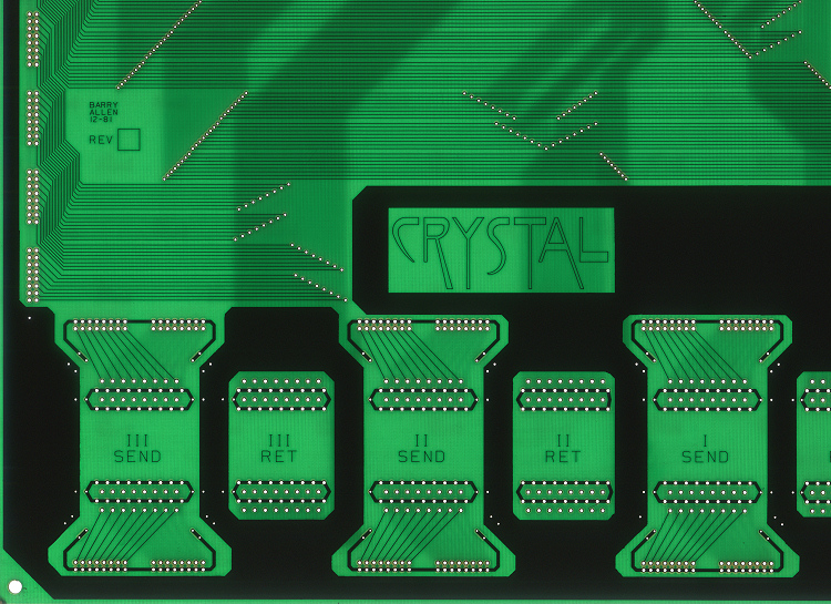
I never really found out who the incredible artist was who did the Crystalab artwork and comics. If you're out there I'd love to know! There are MANY more stories associated with the building of the console(s) and the rooms they were in and that's just for the 5+ years or so that I was there. Here's an example. Studio B was built by Bugs Pemberton, who, as far as I know, was a drummer doing a session, when he lent a hand putting up some wood shelves. Andrew noticed that he had a special talent for woodwork, (one of the understatements of the century) and asked him to build the studio. So he did an incredible job - notice in the picture (which also opens in a larger view to another page) the brown velvet-looking flat sections framed by the quarter-rounds: the velvet sections are wrapped fiberglas sections and the curved parts are cut sonotube pieces, with veneer glued to them. Every screw head has been flush plugged with a contrasting plug. The burl veneer affixed to the machined aluminum top and back of the console has many layers of a clear acrylic, all hand rubbed, and of course ALL the markings line up perfectly. And the amazing picture on the back wall, was placed there in honor of Stevie Wonder. The scene is composed of thousands of inlaid veneer pieces, all flush cut with an exacto knife it's about 7 feet wide. The different parts of the inlaid flowers are scented with essential oils, in honor of Stevie's album, Secret Life of Plants. Also notice the EMT-250, one of Stevie Wonder's. When there were 2 units in the room, we would patch them in a sort of quad feedback loop, adjusting the digital attenuators 1/8 dB at a time, until myriad feedback loops would be produced, in an infinity of 3- dimensional psychedelic electronic music involvement! The bongos as a flower pot were a special touch of the era. The monitor speaker cabinet was also a series of experiments; the sections are separate and we did some tests of what you might call a "mechanical time and phase alignment system" the tweeter could be moved in and out of the cabinet a little bit while white noise was playing, and the imaging would snap to focus. This was one of the earlier tests of my white noise alignment system, a more recent version of which is presented in my "White Paper", HERE. The mixing board described here was the first to use 5534 opamps (and 530's as well) in an audio product. We received special foundry samples color coded with dots and hand serial numbered of various test engineering samples most likely from Signetics. They sometimes came with a secret sheet of paper with matching colored dots which had pencilled-in explanations of the various characteristics of the sample IC's. Almost all the IC's were in ceramic DIP packages with gold mil leads. Similarly, the fets used in the attenuator were some special samples obtained by Carl Todd, one of the other developmental engineers, and a true genius in his own right. I can safely say that in many instances, it was the summation of all our energy that got us through the fine points of the intense R&D associated with this project. For example, this was the first audio board to have both analog and digital clocking circuitry running around inside. We used to do extreme tests to determine (and make sure) that the digital switching current noise did not get into the analog portion. It was discovered that when the segmented LED's used in the numerical display of the dB attenuation would switch, they would introduce noise. So we removed that section of circuit board, and Andrew and I developed a current mirror circuit and a slightly differing bypass scheme; once that was retrofit, you could literally open the gain up full on ALL the channels including the submasters and main faders and then hear absolutely no noise as the displays toggled. One day Andrew had an idea to try a new bypassing scheme. We hopped in his car and went off to one of the magic surplus stores. Some of these stores knew us quite well, and we'd literally take a shopping cart around the back isles filling up small brown paper bags with all sorts of electronic part goodies. Try doing that today! So we returned with a bag of 10 mF tantalums. In those days, as well as today, sometimes the manufacturer marks the + side and sometimes they mark the - side. Andrew spent half the night laying on his back on the floor soldering in well over 100 caps. I came in and then he said "Let's try it!" So he turned on the power and one by one, just like a sci-fi effect in a movie, every cap exploded they were all soldered in backwards ! That was a very welcome moment in what had been a technically very tense couple of months! According to my experiments and exhaustive tests, one of the reasons the mic preamps were so incredibly quiet, and the crosstalk so incredibly low, is a methodology I developed which to my knowledge no one else has bothered to do. The trick essentially is the mic preamps are inverting. Positive pressure on the diaphragm of a mic gives a + voltage on pin 2. The mic preamp has up to 70dB of gain. It is inverting. Then ALL the subsequent circuits are noninverting. That essentially means that any instantaneous current draw into the mic preamp section from the rails is matched and opposite as you go through the rest of the chain. Therefore the current modulation noise on the rails is nullified. However at the "end" you come out with the correct absolute polarity, since all the internal circuitry is unbalanced. It's a unique trick. That's one reason why the noise floor of the entire console was about -90 dBv and the clipping level at +32: that's a 122 dB dynamic range, with ALL the channels set at unity gain, far superior to anything else. It's also worth mentioning that the 0 reference level internally was -6 therefore between "0 VU" and clipping the headroom was 38dB. I am reminded that during one session in Studio B, Roy Thomas Baker was extremely annoyed he couldn't get the equalizers to clip, even when he patched two channels in series! So much for one of his favorite British console tricks! Nowadays the digital attenuator could be built as a substrate, an ASIC, as a LSI, etc. In those days it was on a rather large (11 inches!) PC board, all laid out visually so it could initially be experimented upon. Fortunately most of the breadboarding was "finished" and therefore not too many REV's of the final PC board were necessary. Each section of the resistive ladder described above has a fet around each resistor. There is also an extremely clever part to the circuit which Carl Todd suggested, then we all put our two cents in... when the signal goes through each section of resistive attenuation, that means the FET is off, so the audio is going through the resistor part. When the fet "shorts" the resistor, the audio is going through the fet, therefore there "might" be some distortion. So Carl and Andrew developed a secondary opamp section with an identical FET (in fact the two FETs are on one substrate for thermal tracking) and the second FET is in the feedback loop such that its distortion cancels out any possible distortion caused by the first switching fet. On paper this seems subtle. On the layout board it was a lot of work, but with 12 of these sections in series, every distortion-lowering effort was worthwhile. When we measured circuitry like this, Andrew loathed THD measurements as much as I did. THD measurements are essentially useless, since they do not tell you whether the distortion is even order or odd order harmonic distortion, and they sound completely different. So we used the wonderful HP 3580 and later the 3582 spectrum analyzers for the "cleanest" measurements possible in those days; the only good thing we could do with the THD measuring devices was to use them as a plain ol' AC voltmeter ! |
||||||||||
|
||||||||||
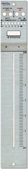
It should also be pointed out that none of these circuits in the console were "cookbook" circuits. Everything was in depth original development by Andrew, Dean, Carl, myself, and some other people who came and went... and there were plenty of instances where we were each surprised at some clever fine point that someone else would think of. There was going to be a microphone level input section where mic tie lines would come in to a multiway connector, then a matching receptacle, then those wires (individual 2-conductor shielded pairs) would go to a connector on each mic preamp... so I suggested that we really didn't need that; why didn't we simply solder the mic tie lines directly from the studio to the input of the preamp? After 3 days of experiments we did just that - Andrew loved it, and he also loved the ease of working with the multipair Mogami wire. A pair of 24-pair cables were stripped back and laced into position. That means that at the far end there was about a foot of extra cable to dress trim, and at the near end there was about 18 feet extra cable to eventually cut off and dress trim. I should point out that every metal to metal point in the console was gold on gold. Every connector had redundant Elco/Edac hermaphroditic pins. Some of the power and ground connections had 2 redundant pins each and some had as many as six. Many of the PC boards I did by hand, at 1:1 on my kitchen table. Some were even two, three, and four layer boards. I set up a pair of 75 watt floods and a pair of dimmers (real autoformers, i.e. Staco) above and below a 1/4" thick piece of matte glass; by carefully varying the ratio of the top and bottom bulbs I could see the tape lines. As soon as I find the Monitor Section of the PC board I will scan and post it. The backplane and larger PC board parts, were done on a very early CAD system by Allen Witters. Allen had one of the very first Computervision CADDS 4 systems on the west coast (if not the first one) and we worked on this design together. Notice in the scan of part of the actual backplane PC board above, we sign our work! The attenuator / fader panel is shown at left. In an age when most equipment was silk-screened graphics on flat painted or stamped aluminum plates, Andrew wanted to simply be better. The entire board visible panels and the undercarriage were all machined T6 Aluminum. Andrew liked to say "My board is made of the same material airplanes and rockets are made of!" The user panels were laser engraved and the engravings filled in with epoxy catalyzed paint. There is simply no way for the markings to come off! Notice even the window bezel cutout for the the "dB ATTENUATION" display LED has a smooth chamfer. After I left Crystal I did not really keep up with the goings-on of the studio, either technically or politically. I know that the studio experienced complicated hard times, and Andrew eventually moved to the Berkshires in Massachusetts. He visited Los Angeles in 2000 and we spent a good day together. Andrew passed away on August 30, 2002. I regard the time I spent at Crystal to be the most rewarding personally and technically of any major project I have ever been involved in. Barry 2010 |
||||||||||
| FOOTNOTES | ||||||||||
| 1 For a comic sans example, click HERE |
||||||||||
|
||||||||||
| THIS PAGE LAST UPDATED October 23, 2019 |